NOVA-DC S2
A dual-socket server mainboard, taken apart one layer at a time. Scroll to open it up.
440 × 300 mm board, 16 layers, 34 modeled parts.
A dual-socket server mainboard, taken apart one layer at a time. Scroll to open it up.
440 × 300 mm board, 16 layers, 34 modeled parts.
Backplates sit under the board. Sockets, memory slots and connectors rise first, then CPUs, load plates, thermal paste, heatsinks and screws.
Each LGA4677 socket takes a 56-core CPU under a nickel heat spreader. A load plate and two levers clamp it onto 4,677 contacts.
A copper plate meets the CPU through a thin layer of paste. Four heat pipes carry the heat into 33 aluminium fins, and chassis fans push air straight through.
Six registered DDR5 modules flank each CPU. Running along the airflow lets cool air pass over every module.
Seven power stages and fourteen chokes per socket, backed by polymer capacitors and two 8-pin 12 V inputs at the rear.
An OCP NIC 3.0 card adds dual 25 GbE. Riser slots, MCIO ports and a BMC with its own flash round out the I/O.
Same board, same parts, assembled. Open the viewer to take it apart yourself.
The same modeling approach covers a 2U server board and a compact desktop board. Each one opens in its own full 3D viewer.
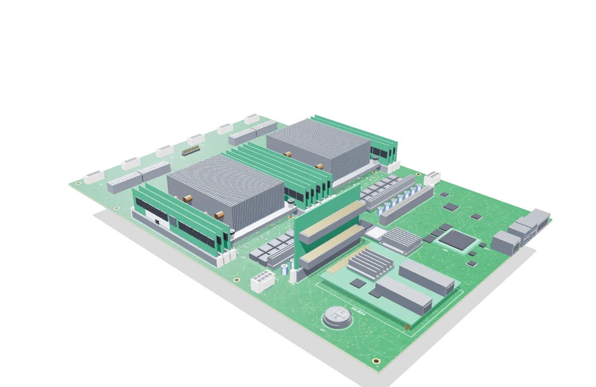
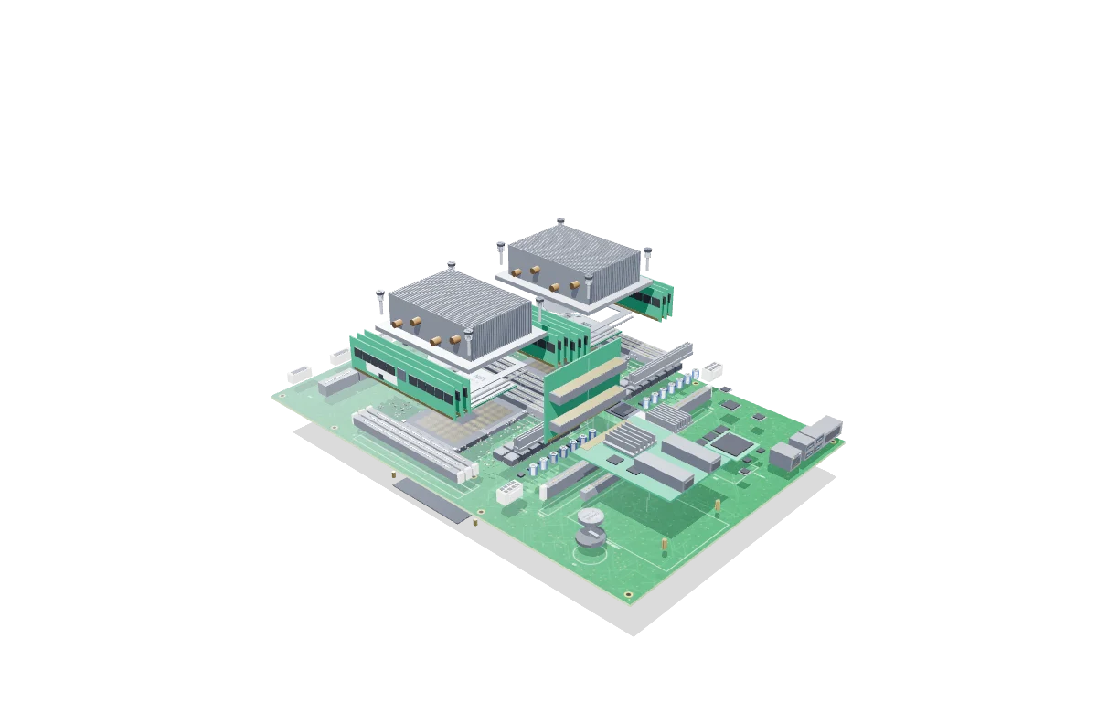
Dual-socket server mainboard for a 2U chassis, with two 56-core CPUs, twelve DDR5 slots and an OCP network card.
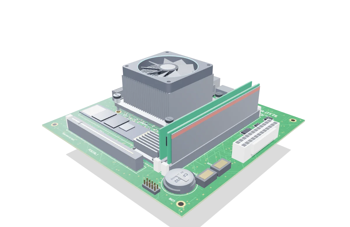
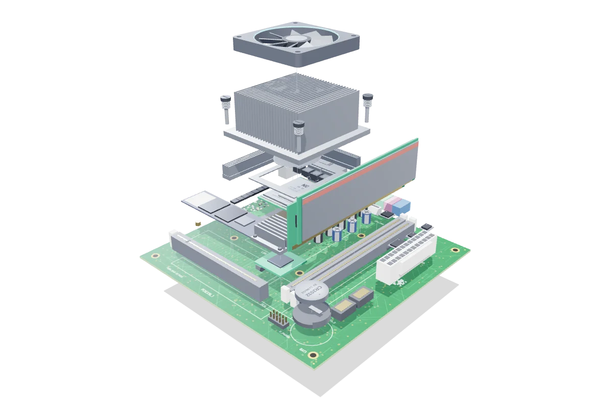
Compact desktop board with a socketed CPU, a spring-loaded cooler with a spinning fan, two DIMM slots and an M.2 drive.
Six assemblies, each isolated from the rest of the stack. Select one to open the viewer focused on that part.
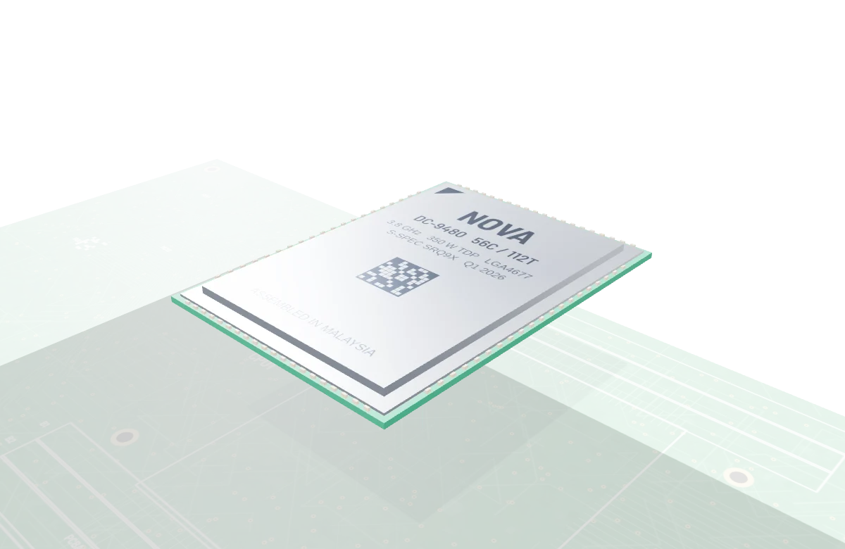
56 cores under a nickel heat spreader, with gold lands on the underside.
Inspect in 3D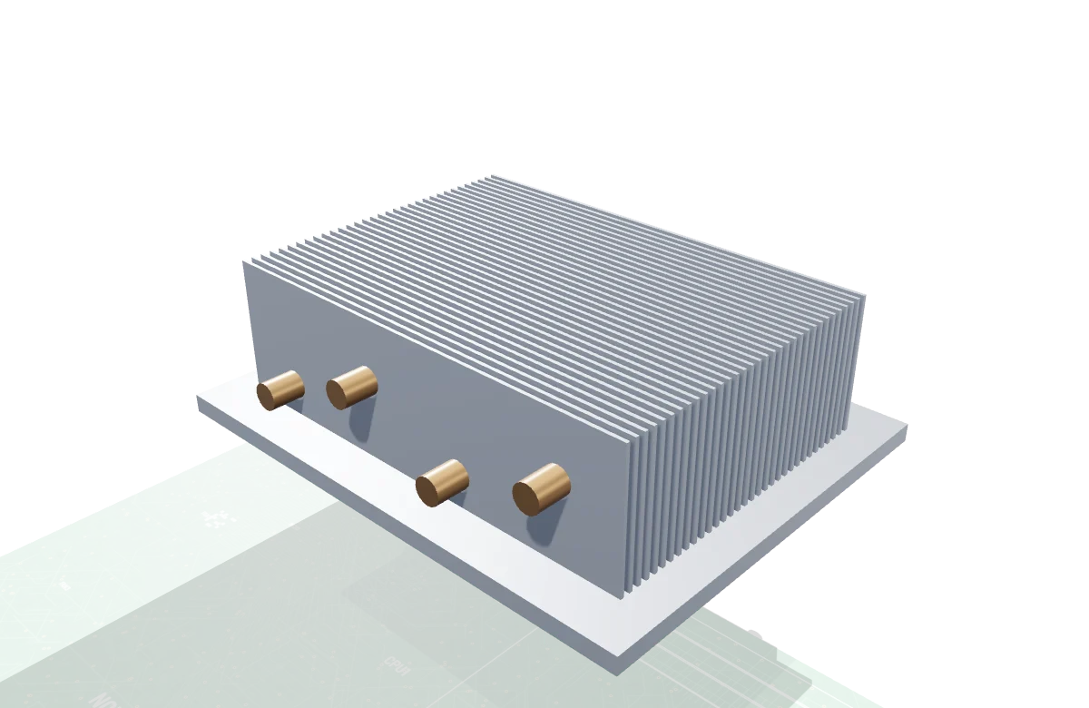
Copper contact plate, four heat pipes and a stack of 33 aluminium fins.
Inspect in 3D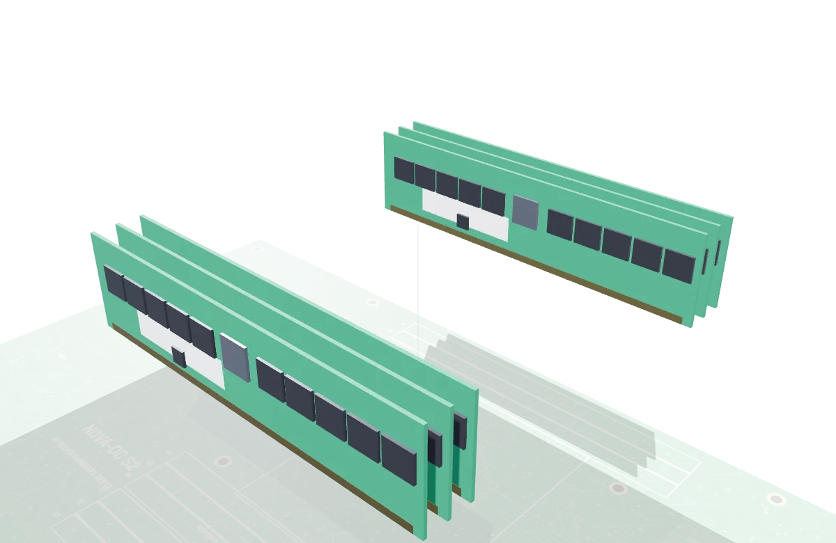
Six registered DIMMs per CPU, ten DRAM chips on each side.
Inspect in 3D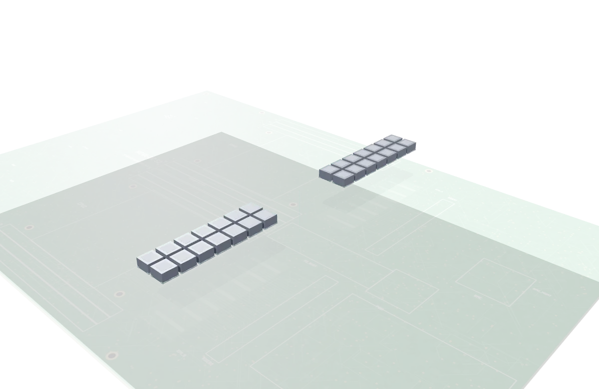
Chokes, power stages and bulk capacitors convert 12 V for each socket.
Inspect in 3D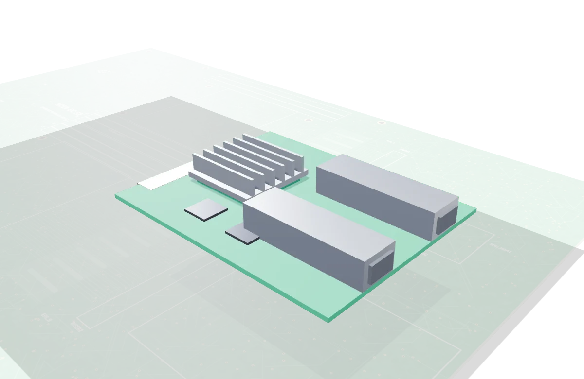
Dual-port 25 GbE card with its own heatsink and two SFP28 cages.
Inspect in 3D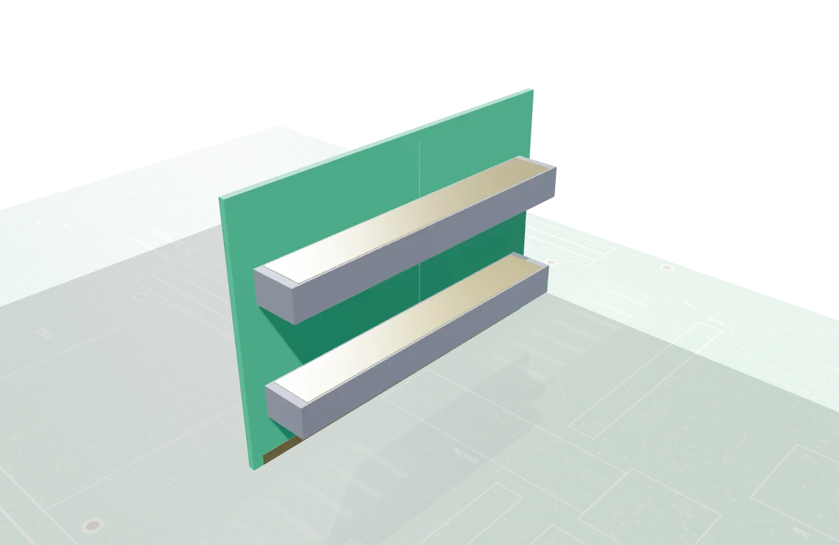
A vertical card with two horizontal slots, so add-in cards lie flat.
Inspect in 3DConcept hardware. Figures describe the 3D model and are illustrative, not a shipping product.
440 × 300 mm, 16 layers, 2.4 mm thick
Two LGA4677 sockets, 56 cores and 112 threads per CPU, 350 W each
Twelve DDR5 RDIMM slots, six per CPU, parallel to airflow
Two PCIe 5.0 x16 riser slots, OCP NIC 3.0, four MCIO x8 connectors, M.2 2280 boot slot
BMC with SPI flash and DRAM, dedicated management Ethernet, VGA, two USB 3.0
Two 8-pin 12 V inputs, seven power stages and fourteen chokes per socket
Passive 2U heatsinks with four heat pipes each, six 6-pin fan headers
34 separately selectable parts, rendered live with Three.js
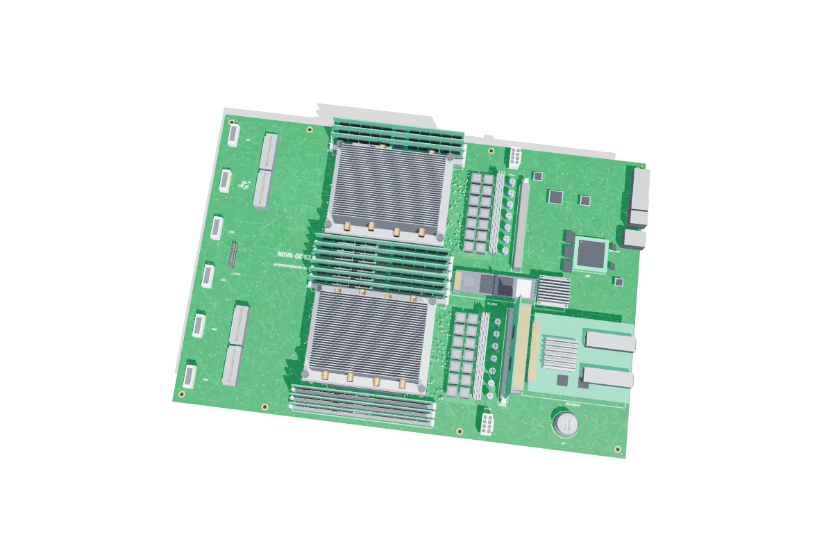
Three decisions shaped the layout.
DIMM slots and heatsink fins run front to back. The power stages sit downstream of the CPUs, and the fan headers line the front edge.
Each CPU has its own memory, power stages and PCIe lanes, so the board reads as two identical halves with shared I/O.
Every layer is separately selectable in the model, so the explode order doubles as an assembly and service sequence.